Build Mode: Operation Guide
Official Website:
xlands.com
Document directory:
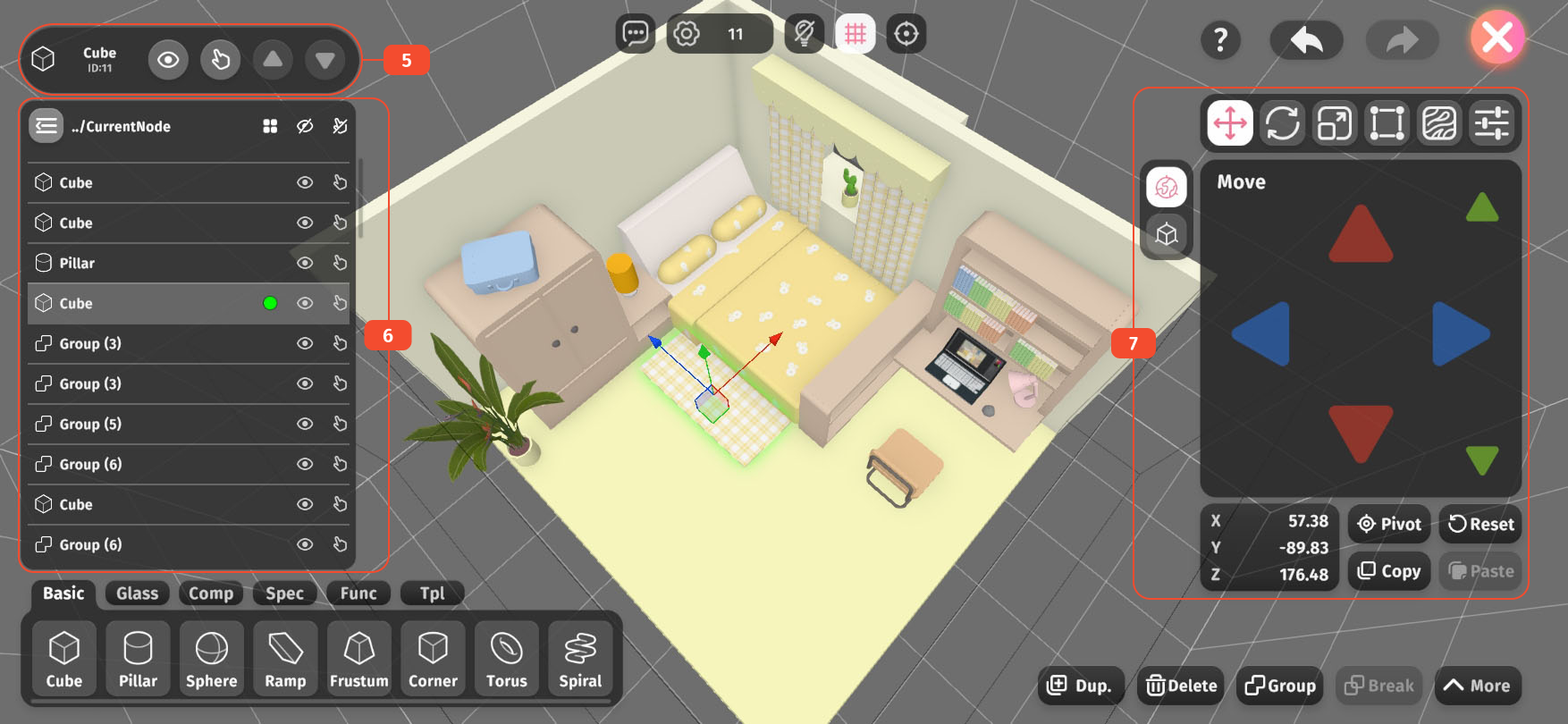
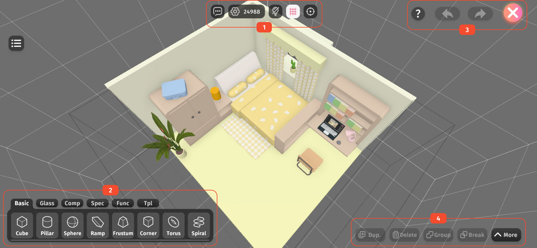
As shown in the two pictures above, we can roughly divide the UI of the building mode into the following sections according to the areas divided by the red boxes in the picture.
From left to right they are: Enter builder chat room、Build settings、Show/hide light and shadow、Show/hide grid、Focus button.
The numerical representation on the Build settings button shows Complexity. When there is an object currently selected, it shows the complexity of the object, and when no object is currently selected, it shows the total complexity of the scene.
Click an object in the menu to add it to the scene, and the menu bar can be dragged left or right.
Different menu pages contain several different categories of objects:
Undo and redo can record up to 64 recent operations.
Undo and redo only include editing and selecting operations on scene objects.
Operations such as modifying build settings, importing or deleting templates or textures cannot be undone or redone.
All modifications made while editing the scene will be saved immediately, and there is no need to save manually when exiting.
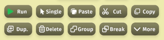
Mainly includes operations targeting objects, such as duplicating, copying, pasting, deleting, grouping, ungrouping, etc.
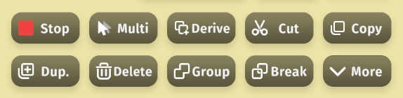
The toolbar has two layers. Click More button to expand/collapse the second layer of operation buttons, as shown below.
The Single (select) button is a two-sided button, with the back side being a Multi (select) button. Clicking it switches the selection mode. In single-select mode, if A object is selected and B object is clicked, A object will be automatically deselected. In multi-select mode, both A and B objects can be selected at the same time.
The Run button is also a two-sided button, with the back side being a Stop button. It is mainly used for users to test and check whether the functional objects and logic circuits in the scene are operating as expected.
The Paste button is also a dual-function button. After duplicating an object, it turns into the Derive button. The derive function records the differences in position, rotation, and scale between the clone and the original object. It then treats the clone as the base and duplicates again and repeats the same differences to quickly generate a series of evenly arranged objects—such as the hour markers on a clock or a path made of evenly spaced stone tiles.
Only visible when there is a selected object.
The eye icon button serves as a Hide/Show button to toggle whether the object is visible (only effective during editing).
The finger icon button serves as a Selectable/Non-selectable button to toggle whether the object can be selected (this does not affect selection from the object list).
The upward triangle icon button serves as the Float Up button, which is only available when you've dived into a group object, and it allows you to return to the hierarchy level of the group object.
The downward triangle icon button serves as the Dive Down button, which is only available when a single group object is selected, and it allows you to dive into the group to edit the objects inside.
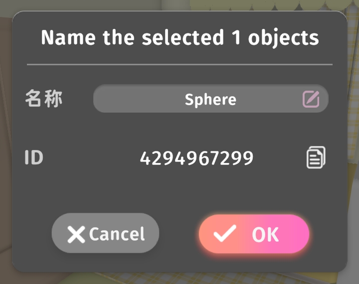
Clicking the object icon and name area on the left side of the name bar opens the Object Name Popup as shown above. In this popup, you can edit the object name and copy the object ID (used for logic circuit configuration).
You can expand or collapse the object list by clicking the Expand List button in the top-left corner of the screen, or the Collapse List button in the top-left corner of the list.
The object list includes all objects in the scene, with each item in the list representing an object.
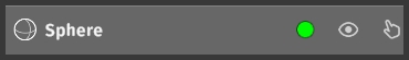
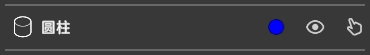
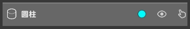
As shown in the image above, the eye and finger icons on the right side of the object entry not only indicate whether the object is visible and clickable, but also serve as quick buttons to toggle these states of the object.
A circular color marker on an object entry indicates its selection status:
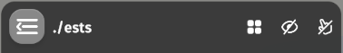
As shown in the image above, the text in the top bar indicates the current hierarchy level (blank means the root level). In the example, the objects are in the "ests" group level.
The eye and finger icons on the right side of the top bar serve as All Hide/Show and All Selectable/Non-selectable quick buttons, allowing for bulk modification of visibility and selectability for all objects in the current level.
The matrix icon on the right side of the top bar is the Select All button, which allows you to quickly select all objects in the current level. Clicking the top bar text or empty areas will also achieve the same effect.
Only visible when there is a selected object.
For details on object properties, please refer to the section below.
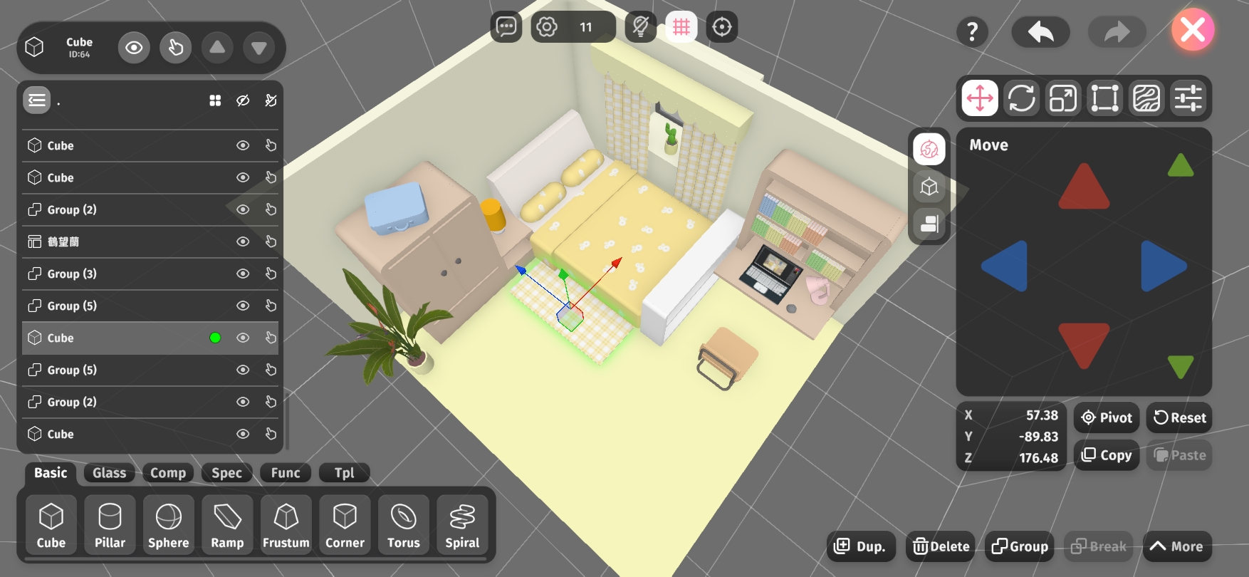
There are six tabs for object properties, listed at the top from left to right: Move, Rotate, Scale, Rect Transform, Material, and Properties. Tap a tab to switch to the corresponding section.
The left-side panel contains coordinate system options and a multi-object alignment tool. From top to bottom, they are: World Coordinates, Local Coordinates (only differs when the object is rotated), and the Alignment Tool.
In the center is the control pad, with red, green, and blue representing the X, Y, and Z axes. Tap the buttons or slide your finger across the pad (left-click and drag on PC) to adjust the object's position.
The three axis lines and the colored cube at the object's center are also handles you can drag to adjust directly. The same interaction applies to Rotate, Scale, and Rect Transform, which will be explained later.
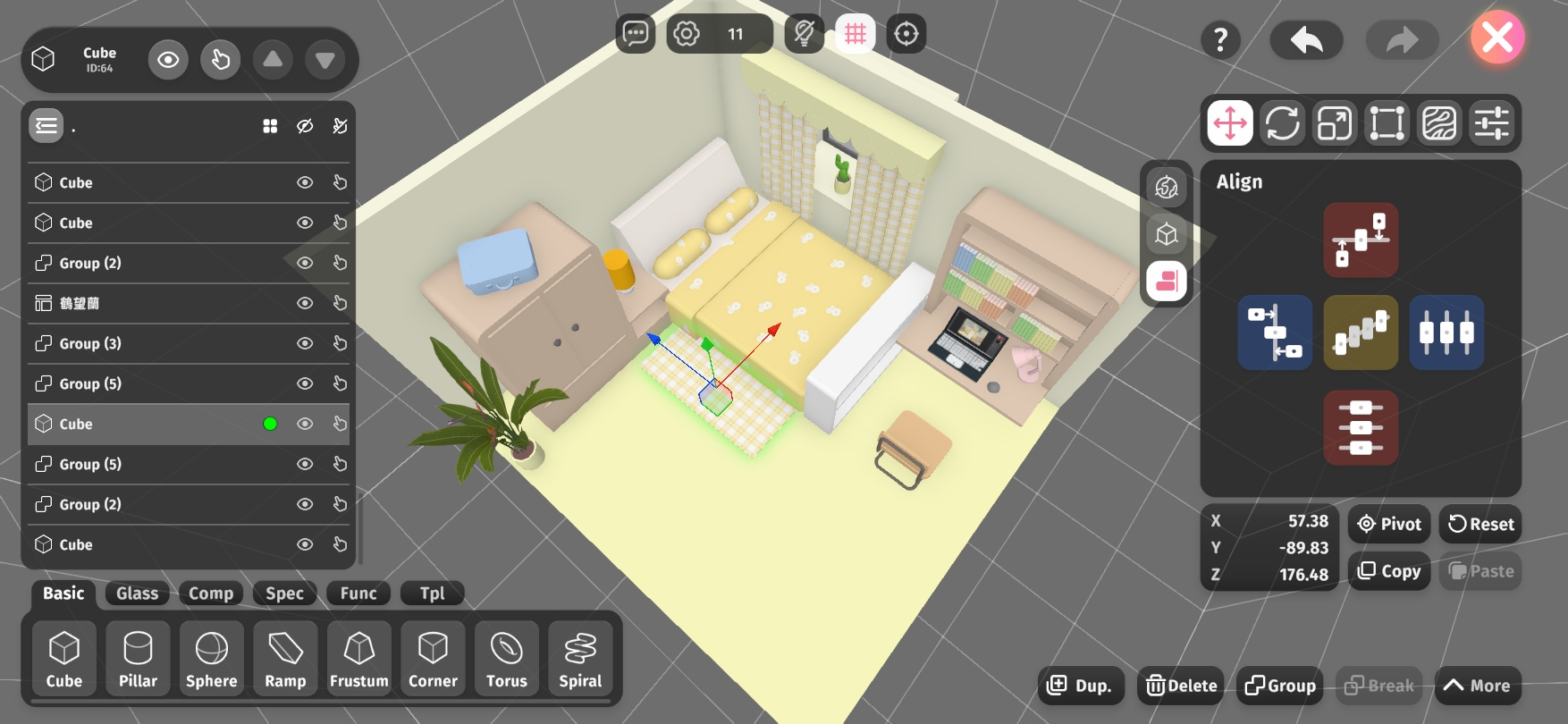
When you click the Alignment Tool in the left-side panel, the control pad switches to the alignment options shown above.
At the bottom left is the XYZ coordinate panel. Tap it to open a precision adjustment popup, where you can enter exact values or reset individual axis values to 0.
The Pivot button opens the pivot settings panel, allowing you to adjust the object's pivot point on each axis.
The Reset button moves the object back to the scene's origin point (0, 0, 0).
The Copy and Paste buttons let you copy and paste the object's position.
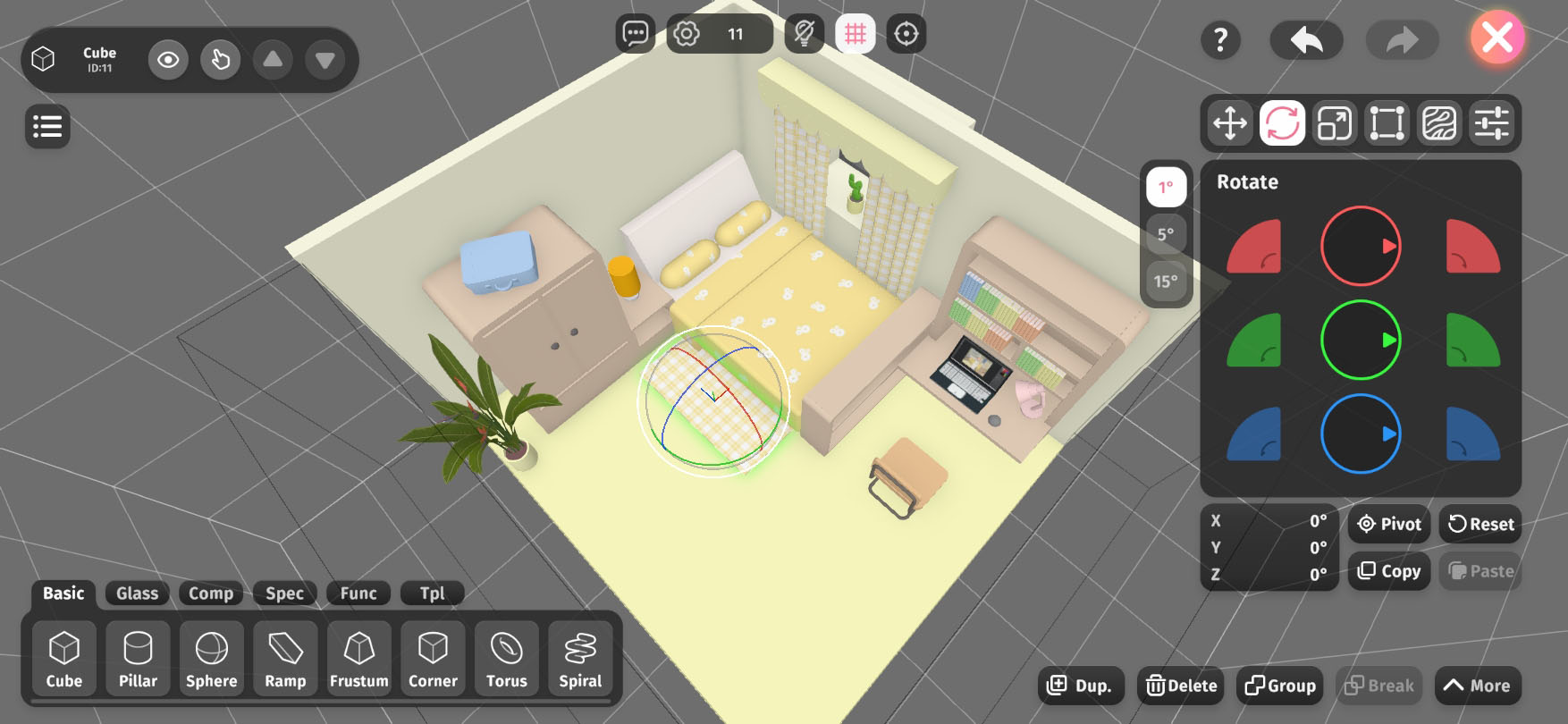
The left panel offers angle unit options, which determine the smallest angle increment for rotation.
In the center is the control pad. Just like with Move, red, green, and blue represent the X, Y, and Z axes. Use the fan-shaped buttons on either side to quickly rotate 90° along the corresponding axis, or drag the center dial left, right, up, or down for free rotation at any angle.
At the bottom left is the XYZ rotation panel. Tap it to open a precision adjustment popup, where you can enter exact angle values or reset individual axes to 0°.
The Pivot button works the same as in Move and shares the same pivot settings.
The Reset button resets the object's rotation to (0°, 0°, 0°) (no rotation).
The Copy and Paste buttons allow you to copy and paste the object's rotation values.
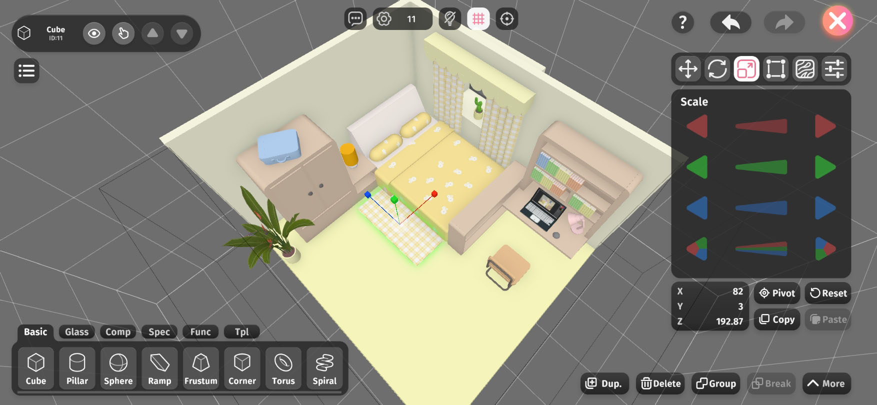
In the center is the control pad. Just like with Move, red, green, and blue represent the X, Y, and Z axes. Use the triangle buttons on either side to scale the object along each axis—left to shrink, right to enlarge. You can also drag the slider in the middle left or right to adjust the scale.
At the bottom left is the XYZ scale panel. Tap it to open a precision adjustment popup, where you can enter exact scale values or reset individual axes to 100.
The Pivot button works the same as in Move and shares the same pivot settings.
The Reset button resets the object's scale to (100, 100, 100) (no scaling).
The Copy and Paste buttons allow you to copy and paste the object's scale values.
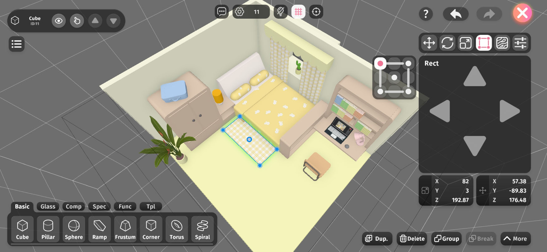
Rectangle Transform is inherited from the Unity3D engine, allowing for convenient, WYSIWYG (What You See Is What You Get) adjustments of an object's scale and position from different viewing angles.
The option panel on the left is the Point/Edge Selector, which determines which point or edge of the displayed rectangle is being controlled.
The rectangle shown on the object represents its cross-section from the current camera angle. You can select its corners, edges, or center point, then click or drag on the operation panel to adjust the object's scale and/or position.
The bottom displays Scale Values and Position Values, which function the same as described in the previous sections.
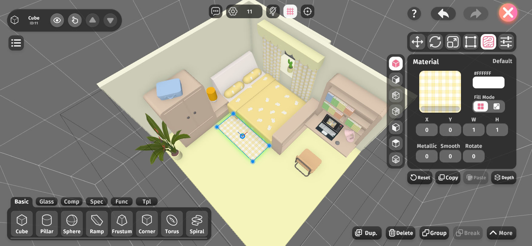
In the Material tab, we can assign different appearances and optical effects to objects by selecting texture maps (default is a plain white texture), adjusting the texture color, and setting the metalness and smoothness of the object.
The left-side options bar contains a surface selection menu. Different shapes of objects have different faces, including the usual top, bottom, left, right, front, and back, as well as inner and cut surfaces.
At the top of the menu is the default face setting. Initially, all faces apply the default face setting. You can use this to quickly set the texture map for all surfaces of the object. Below that are options for specific faces, allowing different material effects on different surfaces of the same object. Once a specific face is modified, it will no longer be influenced by the default face settings.
We offer two Fill Modes for texture mapping: Tiling and Filling.
X and Y are used to adjust the offset of the texture on the object's surface. You can quickly adjust this by dragging the invisible slider on the input field, or click the input field to enter specific values (this applies to other input fields in this tab as well).
W (Width) and H (Height) are used to adjust the size ratio between the object surface and the texture map. Larger numbers mean a larger object surface relative to the texture size.
Metallic and Smooth together determine the optical performance of the surface texture. Larger numbers mean higher metalness or smoothness.
Rotate adjusts the angle of the texture map attached to the object's surface.
When the default face is selected, a Reset button will appear at the bottom to restore all default material settings to their initial state. When a non-default face is selected, the Reset button will be replaced by a Default button to return the modified face to the default settings.
The Copy and Paste buttons are used to copy and paste material settings for the surface of the object.
The Depth button is used to adjust the texture depth for that surface. This function only applies when certain faces of multiple objects overlap in space. There are three depth levels: Shallow, Medium, and Deep. When surface overlap occurs, the shallower face will cover the deeper face and be displayed. Different depth settings are visually represented by different button icons. If multiple surfaces with different materials overlap at the same depth, surface flickering will occur (constantly switching between multiple surfaces).
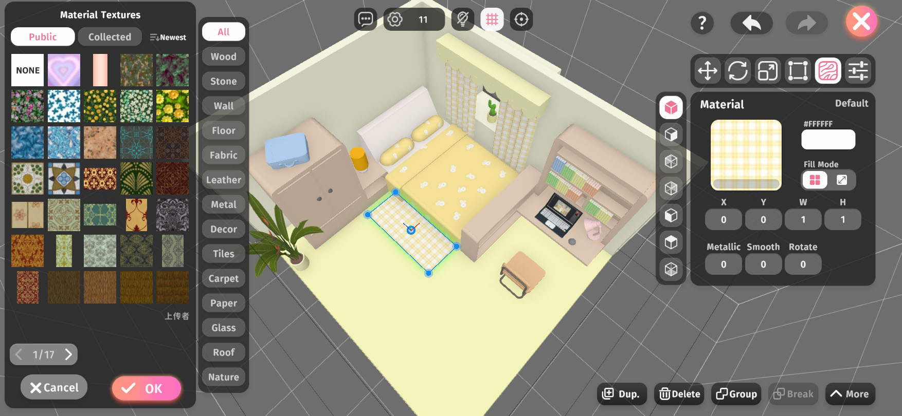
In the Material tab, clicking on the texture image (default is pure white) will open the Texture Library. This library contains various officially preset textures, and users with a Pro-Architect membership can also upload their own textures.
The Texture Library is divided into Public (Public Library), Collected (Collection Library), and the Uploaded (Upload Library) exclusive to Pro-Architects. All textures in the Public Library can be collected into the Collection Library by selecting them and clicking the Collect button below, making them easier to find later.
Each texture is assigned 1 to 3 category tags upon upload, allowing users to quickly search using the tag filter buttons on the right side of the Texture Library.
After selecting a texture for the object surface, you need to click the OK button below for it to be applied; clicking Cancel will discard the application.
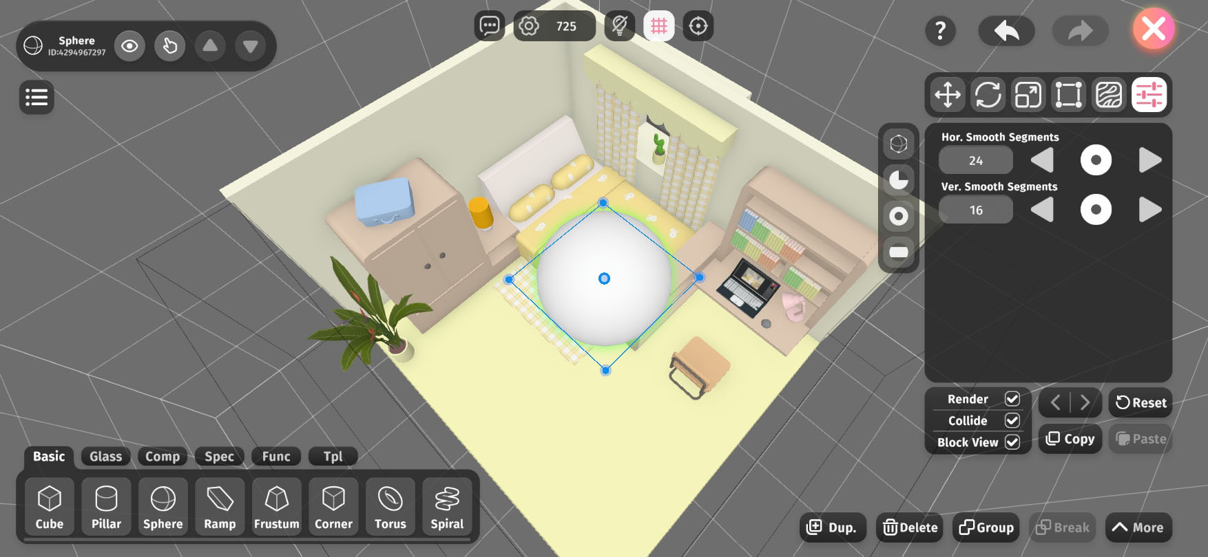
Some shapes have more configurable properties. For example, shapes with curved surfaces will have surface smoothness-related properties. Additionally, some shapes provide variants, such as turning a sphere into a hard-edged diamond shape.
The left tab is for variant application options (multiple selections allowed), offering different variant options for different shapes, such as hard-edging, different directional cuts, hollowing, etc.
At the bottom, there are three checkboxes for universal options that apply to all objects. Render determines whether the object will be displayed in the scene (this can be used to create invisible walls), Collide determines whether the object will block character movement, and Block View determines whether the camera will adapt its distance when the object enters between the character and the camera.
The Reset button restores the object's configurable properties to their initial state.
The Copy and Paste buttons are used to copy and paste the object's configurable properties, excluding universal options like whether to render.
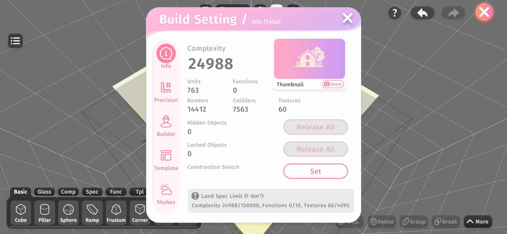
In the Build Settings, you can:
Different land sizes have different scene specification limits. Complexity is a general metric that is influenced by the number of objects, the number of object render faces, and the number of collision faces. There are also specific limits for the number of functional entities and the total texture size in the scene.
The scene thumbnail is a preview image displayed in the Xlands World interface's scene list. In the Build Settings, you can preview the current scene thumbnail at any time or shoot a new one.
When there are a large number of objects in the scene and many have been set to hidden or unselectable for convenience during the build process, you might need to batch set them all back to visible or selectable at the final completion or other stages. You will need to use the Release All buttons in the section Hidden Objects or Locked (unselectable) Objects.
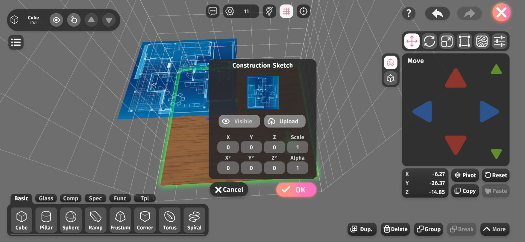
You can add a construction sketch to the scene to better reference drafts such as architectural blueprints during building. Click the Set button on the right side of the Construction Sketch section to open the Construction Sketch Settings Window.
In the construction sketch settings window, you can upload, show/hide the sketch, and adjust its position, scale, rotation, tilt, and transparency. Currently, only one construction sketch can be added to the scene. Uploading a new sketch will replace the existing one.
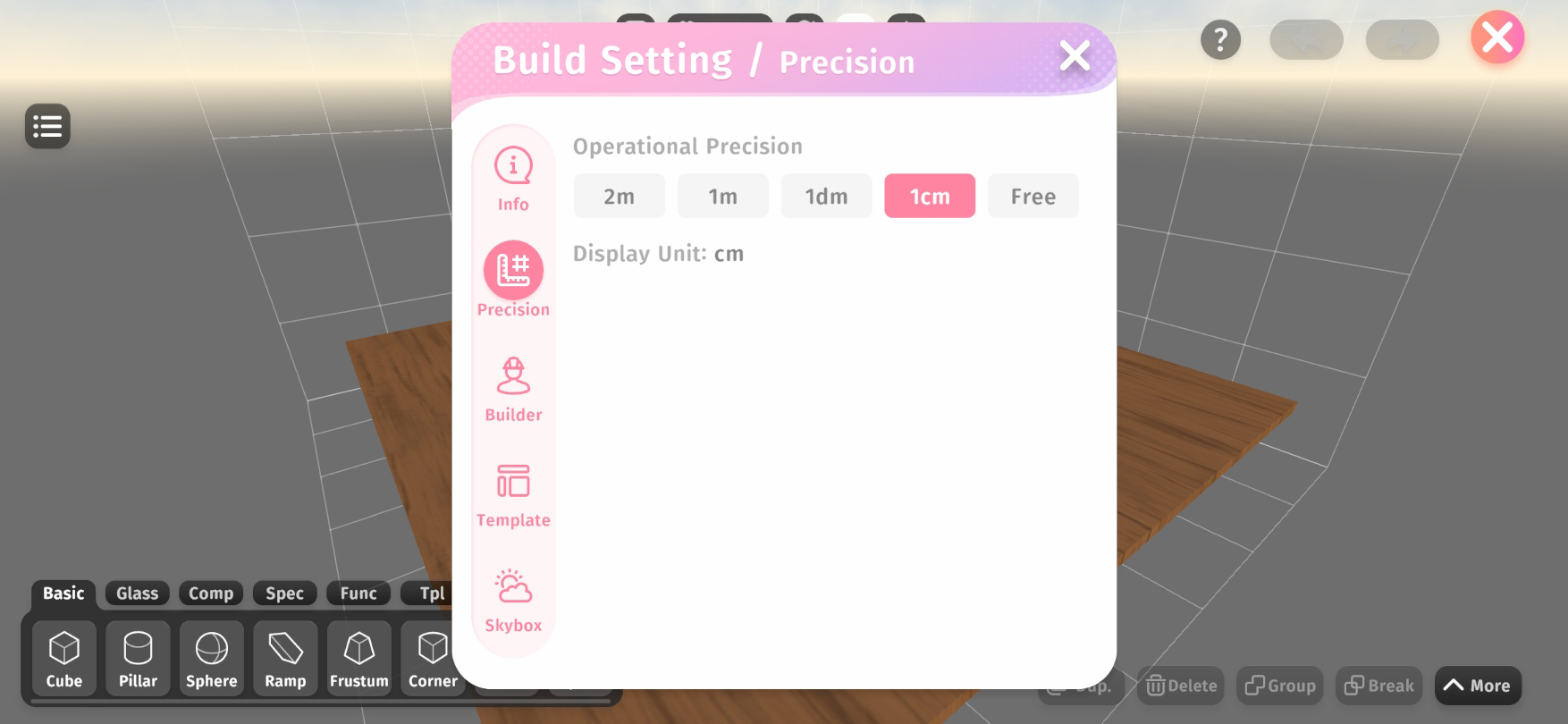
In the Precision tab, you can set the operation precision for building, which defines the minimum adjustment step when moving or scaling objects. Directly entering coordinates or scale values is not affected by this precision setting.
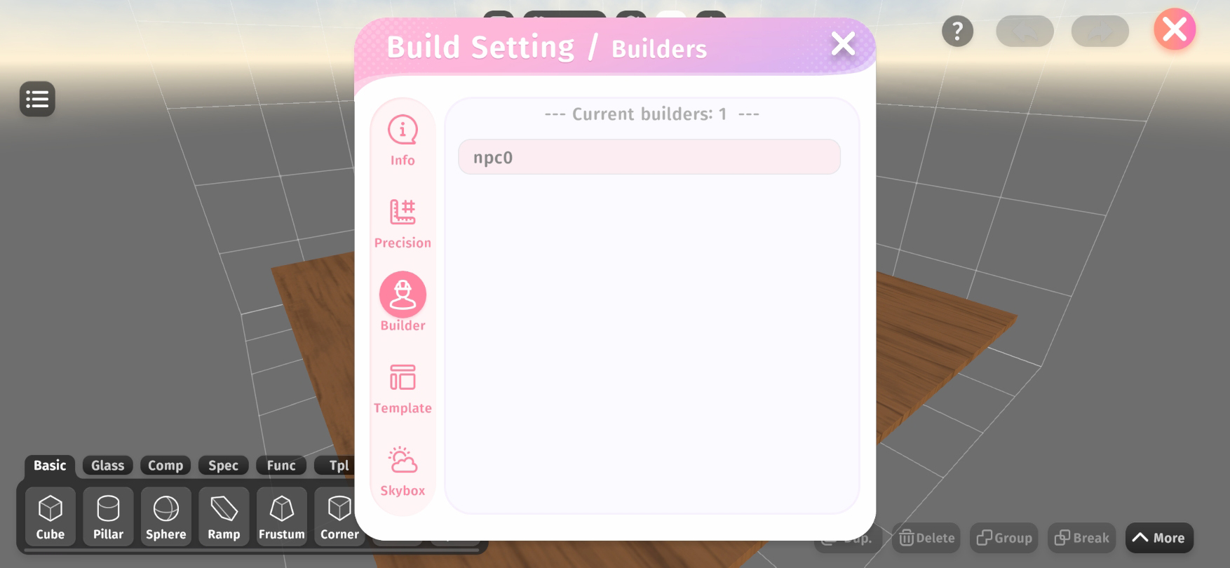
In the Builder tab, you can check the list of collaborators currently working on the scene, making it easier to manage teamwork.
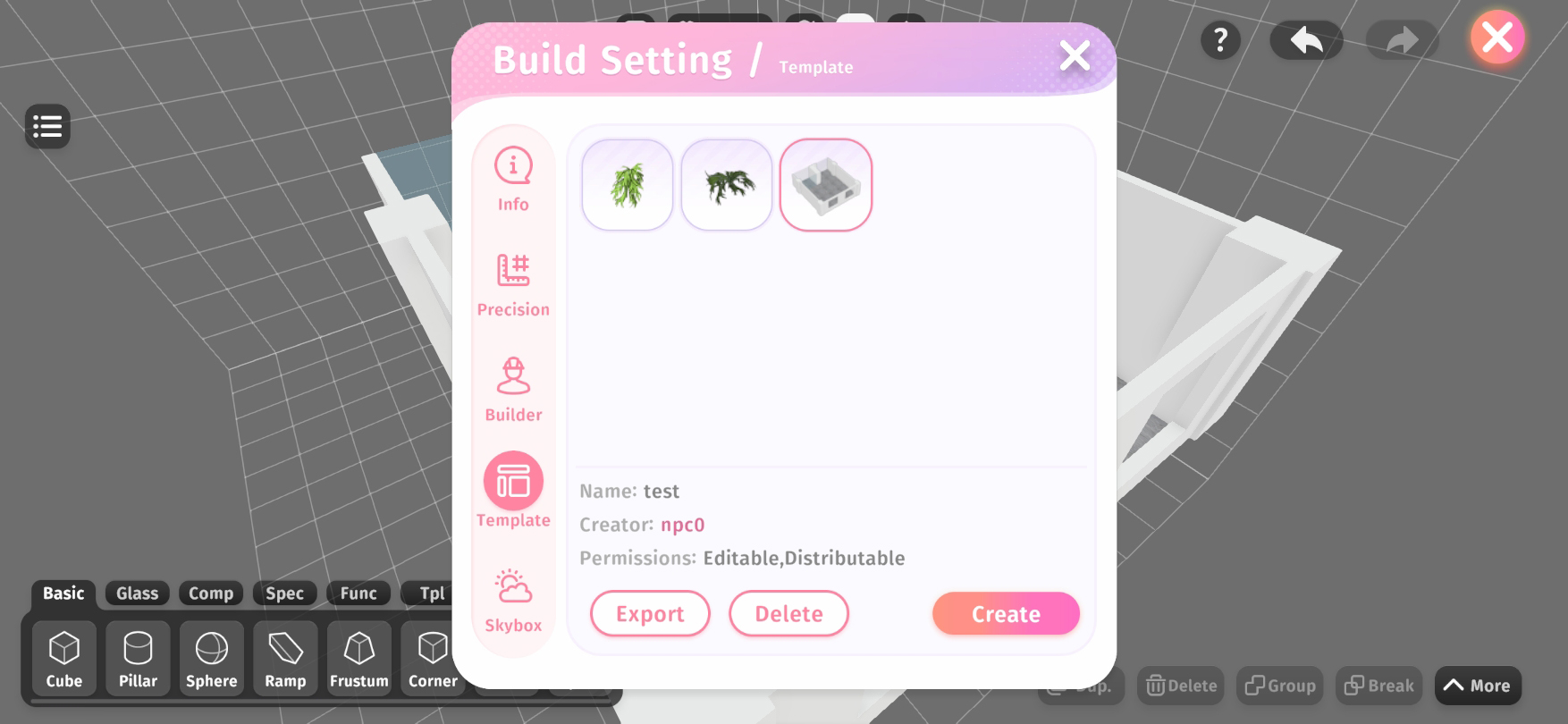
In the Templates tab, you can manage all imported templates, including exporting, deleting, and creating new templates.
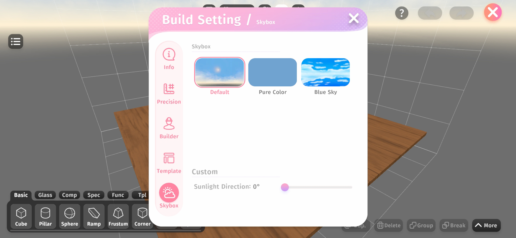
In the Skybox tab, you can select different preset skyboxes for the scene and adjust the sunlight direction.
In addition to the complexity limits mentioned earlier, scenes also have size limits. Therefore, scene limit issues fall into two categories:
When too many objects are added to a scene, it may exceed the complexity limit.
In this case, the number on the Build Settings button in the global toolbar will turn Red to alert builders to reduce complexity. You will no longer be able to add more objects to the scene, and scene access will be restricted to builders only.
To reduce scene complexity, you can:
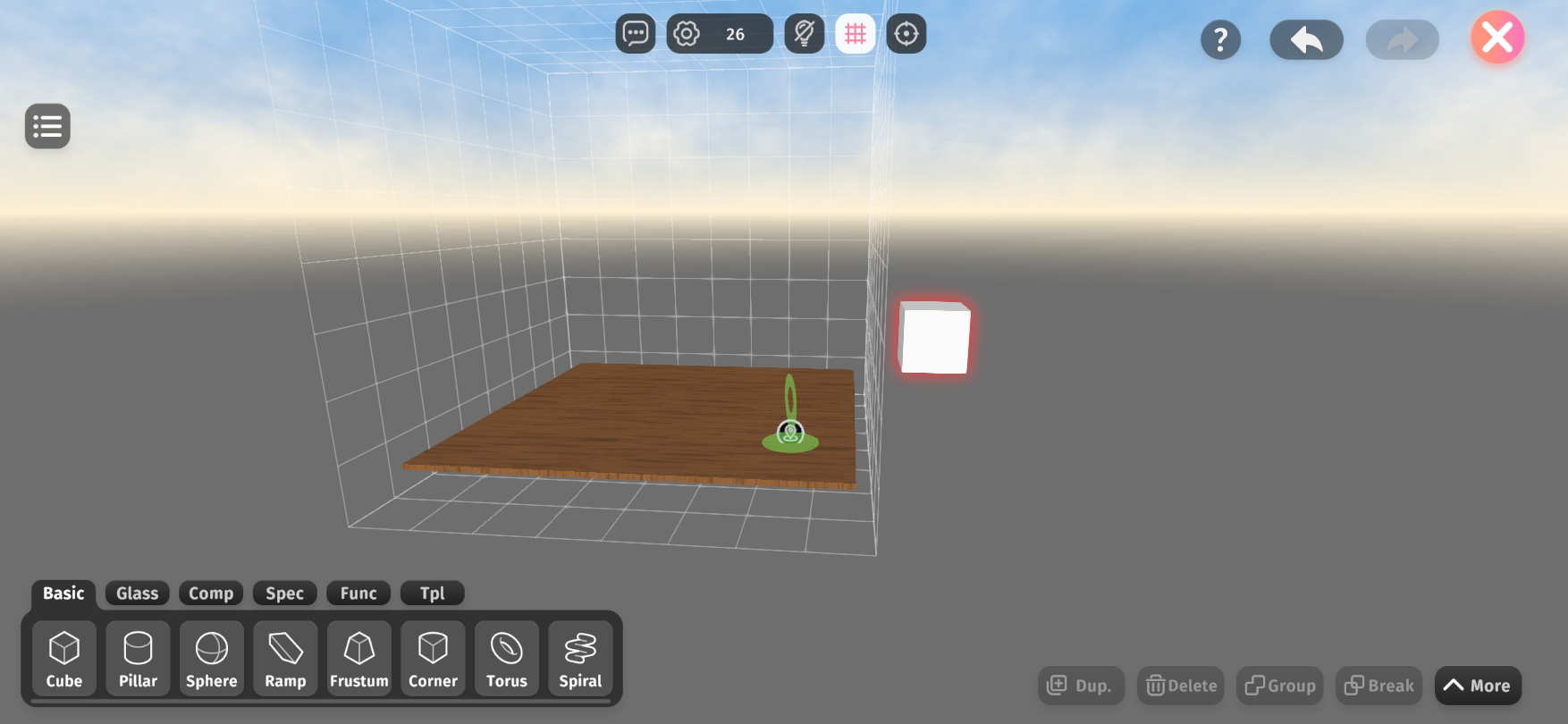
When any part of an object extends beyond the valid scene boundaries, the size limit is exceeded.
The objects causing the issue will be surrounded by a red glow (orange when selected).
Size limit violations do not affect the overall usability of the scene. However, the exceeding parts of objects will not be visible or participate in collision detection outside of Build Mode.
Non-physical objects, such as Functionals, will not trigger size limit issues even if placed beyond the scene boundaries.
On the PC client (Windows or MacOS), the following operations support shortcut keys:
operation | shortcut key |
Delete | Delete |
Undo | Ctrl + Z |
Redo | Ctrl + Y |
Copy | Ctrl + C |
Paste | Ctrl + V |
Cut | Ctrl + X |
Duplicate | Ctrl + D |
Derive | Ctrl + Shift + D |
Group | Ctrl + G |
Break | Ctrl + B |
Enter Group | Enter |
Exit Group | Esc |
Toggle whether the selected object is visible | AND |
Toggle whether the selected object is clickable | R |
Focus the currently selected object | Spacebar |
Move/Rotate/Scale objects with Free precision | Alt |
Move the selected object left or right in the current viewing angle | A / S |
Move the selected object up and down in the current perspective | W / D |
Move the selected object forward or backward in the current viewing angle | Q / E |
Switch the object properties toolbar tab | 1 / 2 / 3 / 4 / 5 / 6 |